DIY USB MIDI footswitch
See my updated Mark II version
Commercial MIDI footswitches are expensive, but you can make your own quite cheaply and easily – especially if you use USB MIDI.
I recently bought an AKAI MPC One as an upgrade to and replacement for the SP-404SX sampler and MIDI-capable Pigtronix Infinity looping pedal I was using.
The MPC One is great for what I want, but it doesn’t have a foot control, which makes it hard to use when playing an instrument that needs two hands. It doesn’t even have a socket for a foot control, but it does have MIDI input. And it has USB MIDI input, which has a few advantages for me:
- It’s thoroughly commoditised and thus cheaper and easier to hook up than old-school current-loop DIN connector MIDI.
- It uses one cable for both power and data.
- It leaves the MPC’s physical MIDI input free for other devices.
I knew that foot control was possible: I’d seen a video in which someone configured a MIDI controller pedal to trigger the Play, Stop, and Reset commands. The only problem? The device in question cost them USD 249 and even then it wasn’t capable of sending more than one SysEx message with a single press, so they couldn’t play from the start without two presses. The updated Morningstar MC6 MKII does at least support multiple SysEx commands, but still goes for GBP 220 round here.
I don’t need screens or a configuration GUI, so I can do it for quite a lot less. Specifically, about GBP 40.
| Item | Quantity | Cost (GBP) |
|---|---|---|
| Hammond 1590XX case (1) | 1 | 16.99 |
| Momentary SPST footswitch (2) | 4 | 10.00 |
| Teensy 2.0 microcontroller board (3) | 1 | 9.00 |
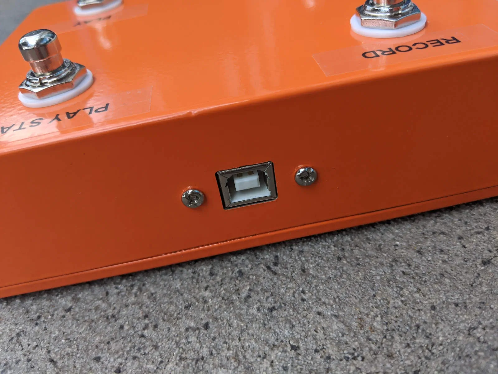
| Panel-mount USB type B socket to A socket extension | 1 | 3.09 |
Plus cable ties, wires, heatshrink tube, sticky fixers, and rubber feet – I used 10 × 2 mm domed feet, but it’s a matter of taste.
Notes:
- I went for a painted case to make it look a bit more finished. The bare aluminium ones are marginally cheaper. I chose orange rather than one of the darker colours so that black text would show up.
- I actually got 5 switches for GBP 10, so I have one spare.
- I didn’t realise at the time, but the board I used is a knock-off Teensy. The real ones are nearly twice as much. I’d probably just use a generic Pro Micro next time, as they cost less than a fiver.
Most of the holes in the case are circular and can just be drilled straight out – I highly recommend a step drill bit for the footswitch holes. The rectangular USB socket required laborious filing, but the end result was good.
I 3D printed some washers to protect the paint, and a little bracket for the microcontroller. The fact that the board doesn’t have any mounting holes made mounting it a bit tricky. In the end, I anchored it with a cable tie around the USB plug. The bracket is attached to the inside of the case with sticky fixers.
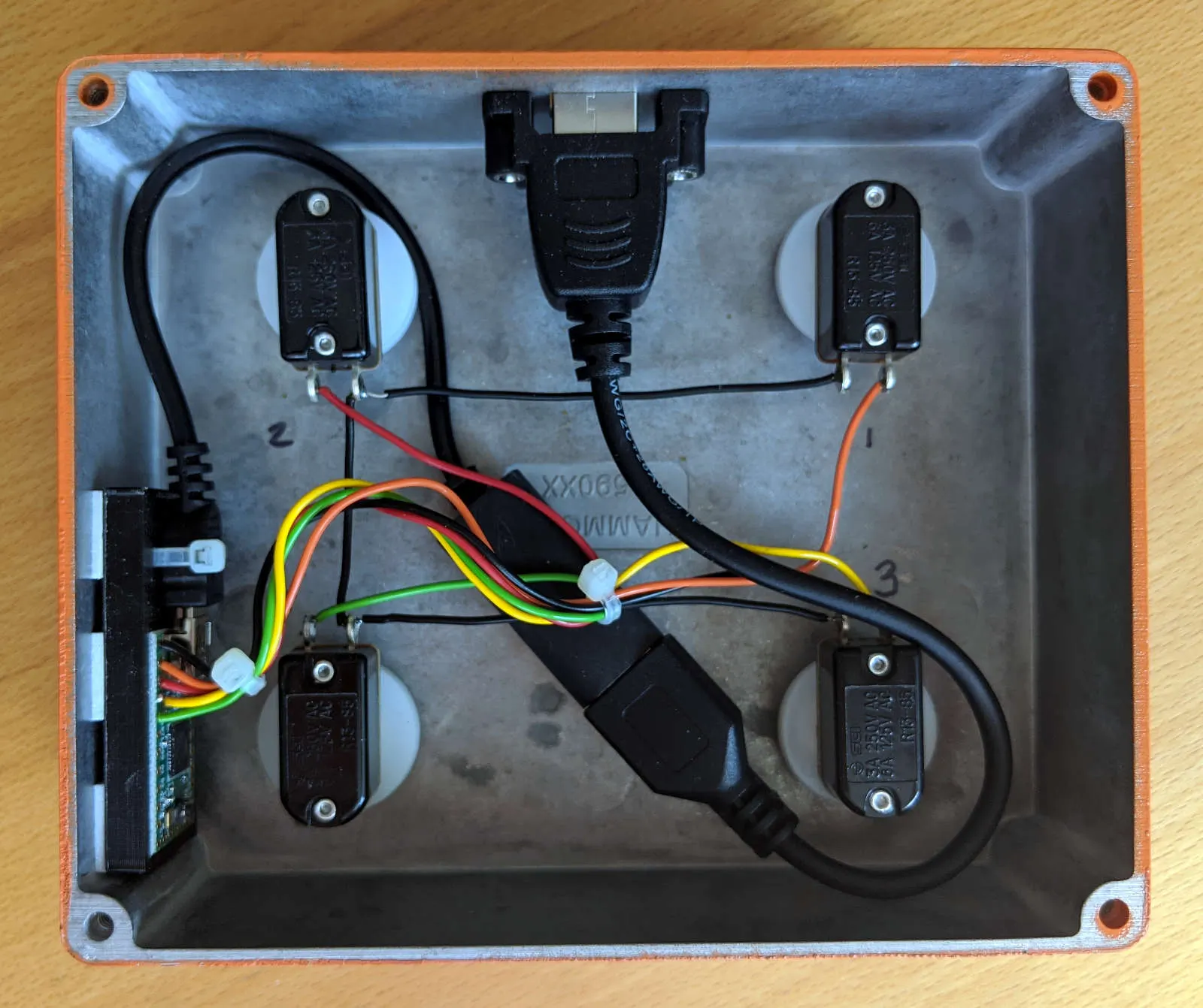
The wiring is very simple: one terminal of each switch is connected to ground (pin 1) with a single piece of strategically-stripped wire, and the other terminal goes to B0, B1, B2, and B3 (pins 2-5) in turn, so that pressing each switch pulls its corresponding pin to ground.
The microcontroller presents itself as a USB MIDI device, and sends hard-coded SysEx commands in response to each button. I wrapped the button debouncing library to add support for different functions on long press – I’m using that to implement Reset via a long press on the Stop button.
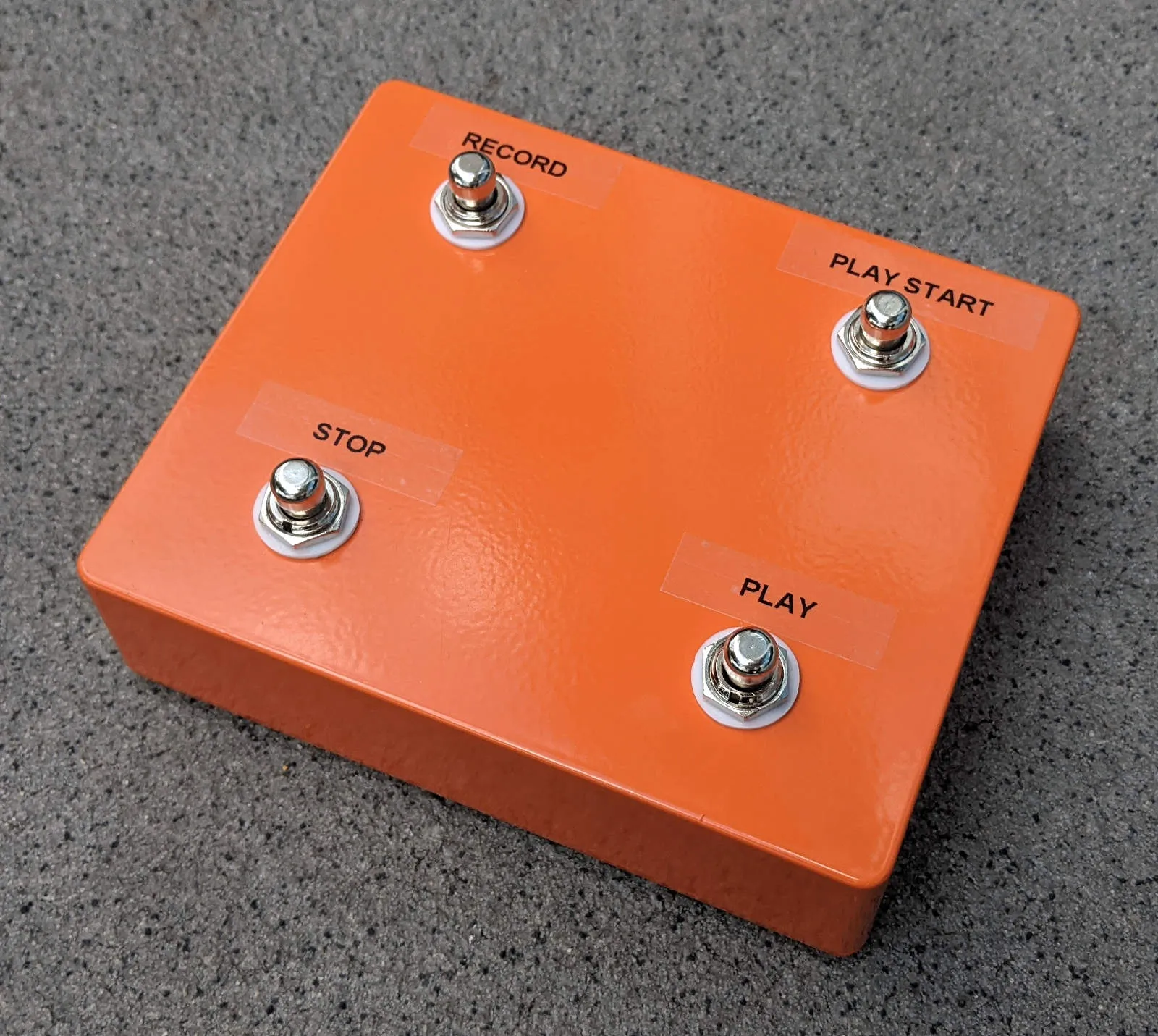
Buttons are labelled with a label printer on transparent tape. I used masking tape for testing until I was happy with the layout.
The code and 3D models are on GitHub. I’ve used the Teensy Arduino libraries, but built with Make, because I can’t stand editing in the Arduino IDE. It’s a bit of a step back when you’re used to a proper programming editor.