Upgrading a Fender Frontman 15G guitar amplifier
When I bought one of my electric guitars, many years ago, the shop threw in a Fender Frontman 15G combo practice amp for free. It was never an expensive amplifier, it doesn’t have a good reputation, and it didn’t sound particularly wonderful.
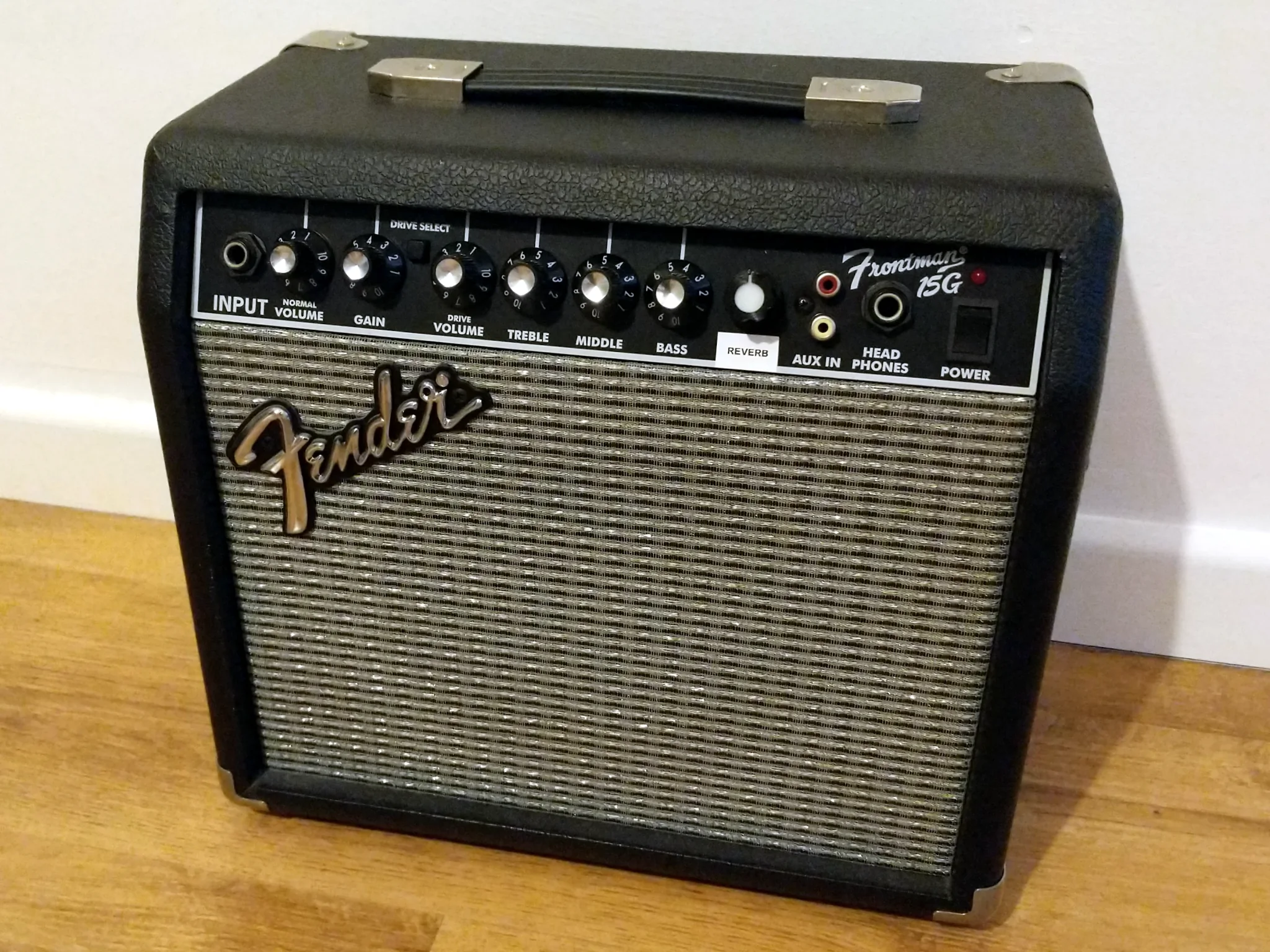
The upgraded amplifier.
However, I recently wondered if I could do anything useful with it, and a bit of searching online led me to a few discoveries:
- The circuit board is shared with the 15R version, which has reverb, so you can add reverb to the amp with only a few £ worth of components and a spring tank.
- The amplifier itself is fine, and people who have used it as a head with a better speaker cabinet have reported favourably on its performance.
- A better speaker is a simple and affordable upgrade.
As it happens, I already had a few spare reverb spring tanks from a job lot of synth parts I bought, so all I needed to add reverb was really just a few passive components and one op-amp.
I found at least one example of someone adding reverb. Unfortunately, most of this was in the form of a video that was taken down by YouTube, so there’s not much detail there.
Adding the missing reverb
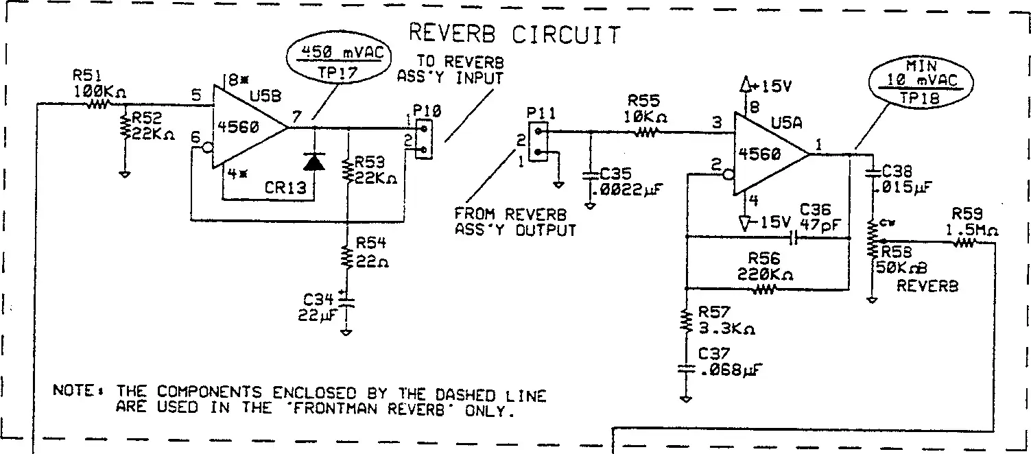
The reverb portion of the circuit. This is unpopulated in the non-reverb version of the amplifier.
With reference to the service manual, I put together a bill of materials:
| Part | Value | Type |
|---|---|---|
| R51 | 100k | |
| R52, R53 | 22k | |
| R54 | 22 | |
| R55 | 10k | |
| R56 | 220k | |
| R57 | 3.3k | |
| R59 | 1.5M | |
| R58 | B50k | 16 mm PCB mount linear potentiometer |
| C34 | 22u | 16 V electrolytic |
| C35 | 2.2n | 100 V polyester film |
| C36 | 47p | 100 V ceramic |
| C37 | 68n | 100 V polyester film |
| C38 | 15n | 100 V polyester film |
| CR13 | 1n4148 | |
| U5 | NE5532 | |
| P10, P11 | 0.1 inch header |
All resistors are specified as ¼ watt, 5%. I used 1% metal film resistors, but all the original parts are 5% carbon.
With the exception of C34, all capacitors are specified as 100 V rated parts. In fact, the preamp section runs off a ±15 V dual-rail supply, so anything over about 35 V would be adequate. Mine were all 50 V or 100 V parts.
The footprint for C36 is designed for an axial package (like C22 in the photo), so I had to bend the legs a lot to use my more common radial capacitor.
The diode CR13 is missed off the parts list. It’s in the negative feedback loop of the op-amp, so it shouldn’t need to handle a high current. I opted for a 1n4148 because I have a lot of them.
The parts list says that U5, which drives the reverb tank, should be a TL072. The schematic specifies a 4560, which is capable of delivering higher current. I installed a socket and used an NE5532, which I know to work in this application, and it does indeed seem to work fine.
You’ll also need RCA cables to connect to the reverb tank, preferably with right-angled connectors to fit into the cramped space. I found the cheapest way was to cut down a manufactured cable.
I used 0.1 inch pin headers and crimped Dupont connectors to connect the cables at the board, but you could equally just solder them directly. The order of connections with the back open and the amplifier upright in front of you is (from left to right) Out Shield, Out Signal on P11 and In Shield, In Signal on P10.
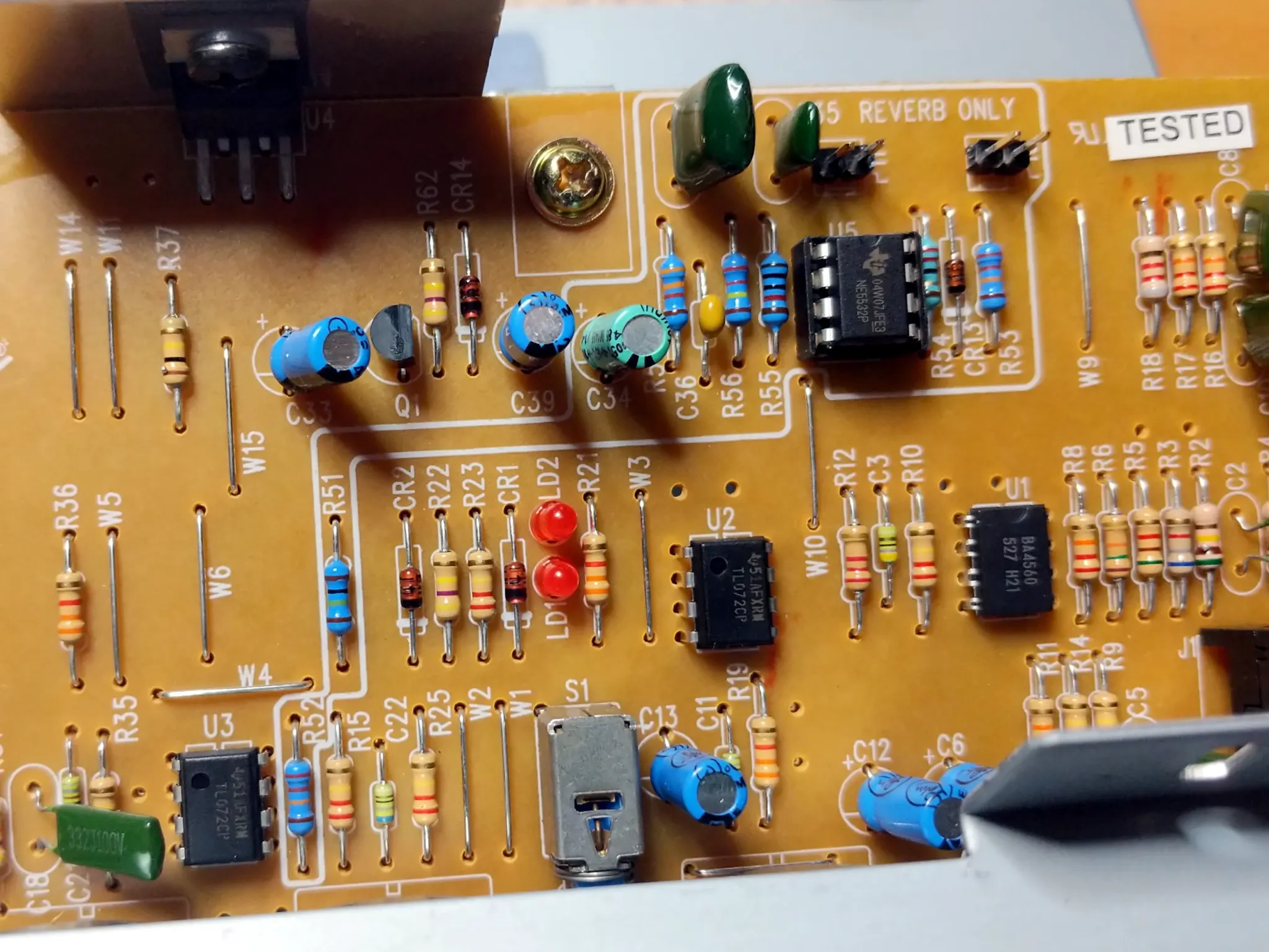
The circuit board after I added the missing parts.
The chassis already has a hole for the reverb potentiometer shaft, but it’s covered by the front panel. However, the panel is no more than a thin sheet of vinyl, and it’s straightforward to open up the hole with some careful work with a scalpel.
There isn’t enough room inside the case to drill, but as it’s all chipboard you can screw directly into it to mount the tank. You’ll need screws of about 15 mm long.
A new speaker
I replaced the speaker with a Celestion Eight 15 (8 Ω to match the factory speaker), which cost me £30 delivered. It’s not a particularly heavy speaker, but it still weighs about twice as much as the stock speaker and showed how flimsy and insubstantial that was.
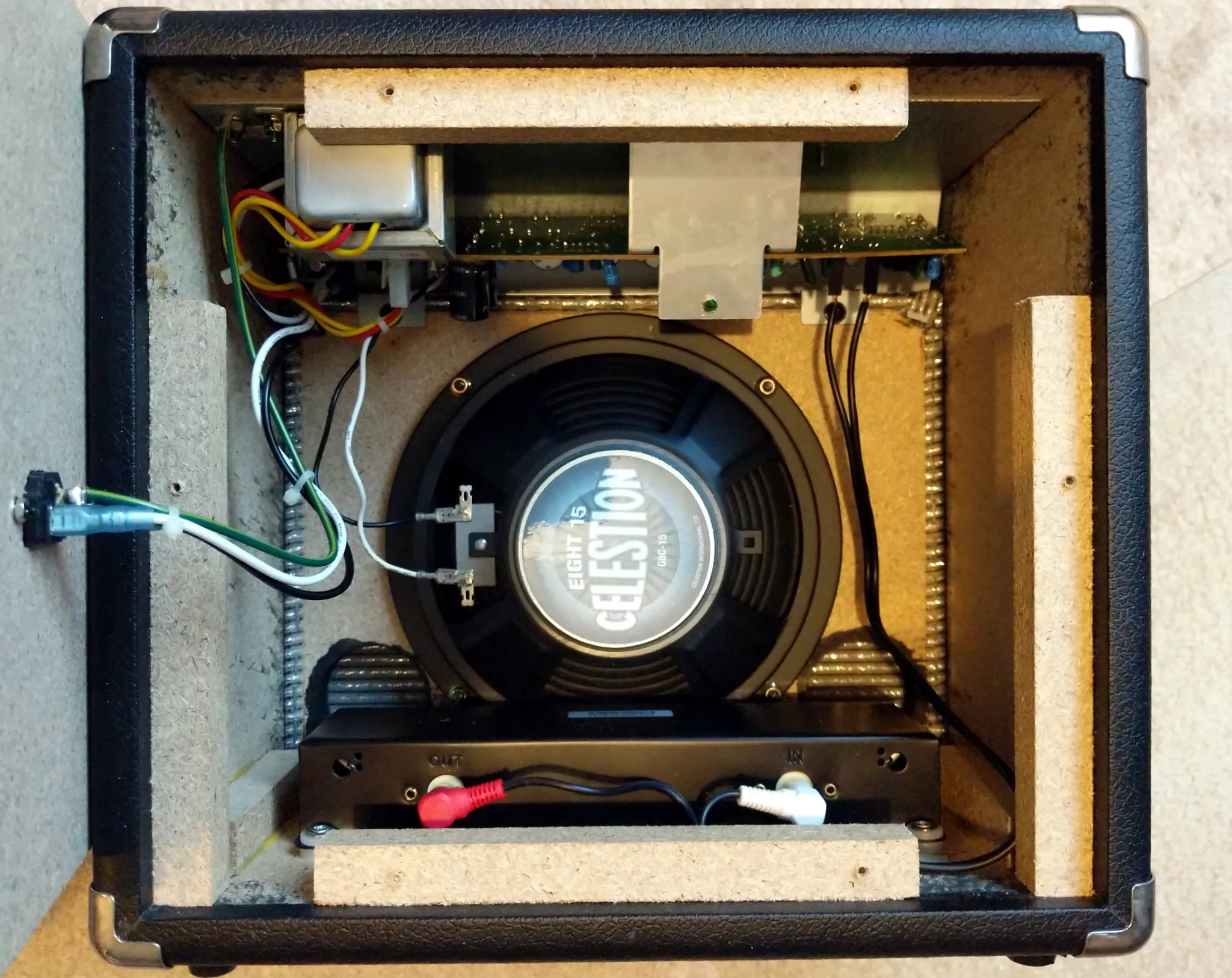
It all fits. Just.
Other changes
I also reduced the gain of the tone control stage (where both the clean and drive input stages converge) by changing R15 from 220k to 100k (a reduction of about 7 dB) in an attempt to make it slightly more manageable at domestic volumes. This has had some effect, but not a huge one.
I replaced one of the red clipping LEDs in the drive stage (LD2) with a yellow one to make the overdrive behaviour slightly asymmetric (but only slightly: there’s not a huge difference in characteristics between the two types). Without the opportunity to A/B test it, I can’t say how much difference this has made, but I like how it sounds.
I still need an appropriate knob for the reverb. I’m using a 3D printed one I had lying around for now.
But what is it like?
The speaker makes a significant improvement to the sound: it has a much stronger low frequency response, which makes it feel fuller and larger than its small cabinet. Before the change, the amplifier was something that made the guitar louder; now, it’s part of the instrument, and making a positive contribution to the tone.
The thing that makes the biggest difference, though, is the reverb. It’s so much more fun and inspiring to play, and when I turn it down to remind myself of what the dry signal sounded like, it’s boring by comparison. With a little drive and a generous amount of reverb, I enjoy playing a guitar plugged straight in, with no other effects.
Is it worth it? Well, it was for me, but I enjoy fiddling with electronics and I already had most of what I needed.